We publish a lot of free open source software and hardware on the directors Codeberg pages. This includes a number of circuit board designs and associated software.
If you have any questions, please contact the specialist PCB support team at pcb@aa.net.uk (please don't call the normal sales staff).
We sell on Amazon, and on Lectronz (which can handle hassle free US and EU sales).
These are sold as assembled printed circuit boards, much as if you were ordering boards from a PCB manufacturer, and as such are not a complete product. They typically come in a PCB biscuit with blank panels you have to snap off (they are V cut, so snap off easily). You can use them as you wish, and they are ideal for a hobbyist or making prototypes, but if you were to use them to make a product that you put on the market you are responsible for ensuring EMC and regulatory compliance for your product as a whole. They do not come with a case or housing, so please ensure you observe ESD precautions to avoid damage (which may not immediately be apparent). Just to be clear, if popular, we may decide to make some of these a "product" in the future, with certification for CE/UKCA marking, but these are current only sold as components - assembled circuit boards.
Support for the physical boards is provided by us, i.e. we will replace a faulty board, or you can return to Amazon if you purchased from them. Contact pcb@aa.net.uk for help.
Support for software, bugs, and feature requests, are handled on the relevant Codeberg pages via issues and discussion pages, but this is open source code with no warranty, so please be nice.
Most boards have open source software available on the Codeberg links shown. This is normally pre-loaded for your convenience, and then allows over the air updates over WiFi. Note that any software pre-loaded is just for your convenience and not part of what you are buying - it is open source software issued on a GPL licence which is "AS IS" with no warranty.
You can also make your own software for these boards. You will need a suitable lead to program them...
These modules are based on the ESP32 processor, so the ESP IDF development environment is recommended (though there is also an Arduino based IDE).
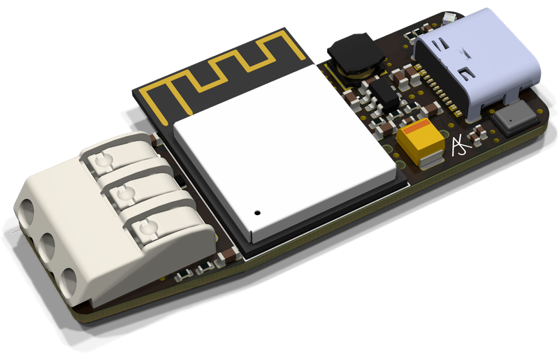
Boards with a processor (most of them) are all designed around the ESP32 processor. The latest boards use the ESP32-S3 processor (specifically the ESP32-S3-MINI-1-N4R2 module). Some of the older designs (and where space is an issue) use the ESP32-PICO-MINI-1-N8R2 module. There are builds for several variants of processor including the SOLO (single CPU) versions in the Shelly devices.
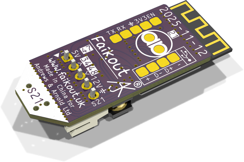
Schematics and PCB layout are all included in KiCad format, along with production files. Note that the AJK, Faikout, and A&A logos are trademarks so should be removed if you make your own boards.
For most boards a 3D printable case design is also included on the Codeberg link.
The boards all have a date code, and the Codeberg project may have moved on since the boards were made. If you have any problems it is worth checking out the project from the corresponding date. This will provide the correct schematic. This is particularly important for the 3D printed cases based on the PCB design as other date codes may not fit. This also means boards you buy may not look exactly like the latest image or circuit. Colour may also vary as I like to make slightly different designs with different colours.
If using the open source software, this is usually set to auto updated periodically - this can be disabled in settings if you prefer. Solar System has its own software update process from the management system.
We have worked through many connector designs - the latest is using WAGO push down connectors with push in wires. Some boards have had screw terminals or 0.1" square pin headers. Some have used Phœnix Contact connectors as they have push in wire plugs (which work best with solid wire). See details for the individual board.
We sell on Amazon, and on Lectronz (who handle hassle free US and EU sales).
If you need similar boards designed, do get in touch. Generally we have experience doing small boards, and using ESP32-S3, USB-C, small switched mode power supply or USB+LiPo charging, small WS2812 style on board LEDs, and a variety of small peripherals, but we can consider other designs. We can usually get batches of boards within 2 weeks if needed.